Module d’affichage à matrice de points 8×8 SPI et MAX7219
5,90€ TTC - 4,92€ HT
Les clients ayant consulté cet article ont également regardé
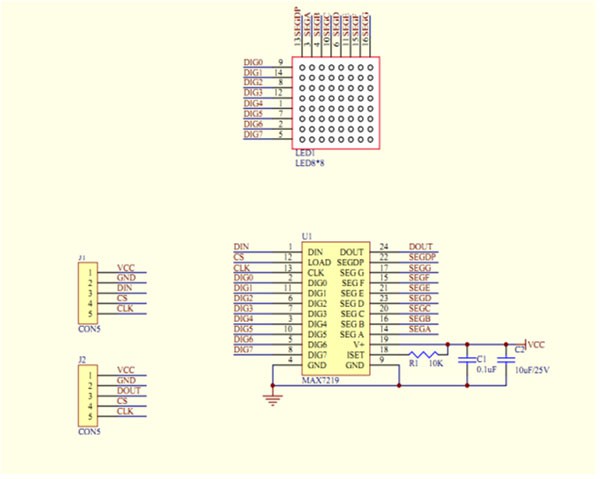
Le module utilise un bus série constitué de 3 fils : un fil CS qui sert à sélectionner le MAX7219 et à latcher les données dans le circuit (les stocker), un fil CLK qui rythme l’envoi des signaux, et enfin un fil DIN qui reçoit les données + 2 fils pour son alimentation.
Il peut être utilisé pour faire des panneaux d’affichage électroniques et vous pouvez rendre vos applications plus vive en raison de l’ajustement de la luminosité LED qui peut être implémenté dans le logiciel.
Wiki et Liens externes
- Manuel : http://www.elecrow.com/wiki/index.php?title=LED_matrix_kit
- Datasheet MAX7219 : http://www.elecrow.com//download/MAX7219.pdf
- Démo sur la matrice de LED 8×8 pilotée par un MAX7219 sur le Raspberry Pi via python http://raspi.tv/2013/8-x-8-led-array-driven-by-max7219-on-the-raspberry-pi-via-python
- Un projet de journal lumineux sur le site Instructables : http://www.instructables.com/id/16×8-LED-dot-matrix-with-MAX7219-module/
(Traduction en préparation)
Product Description
MAX7219 is an integrated serial input / output common-cathode display drivers , which connects the microprocessor 7-segment digital LED display with 8 digits , bar graph can also be connected monitor or 64 separate LED. On type B BCD encoder includes an on-chip , multi-channel scanning loop , segment word drive, but also a 8×8 static RAM for storing each data . Only one external register is used to set the segment current for each LED .
A convenient four-wire serial interface can connect all common microprocessor. Each data can be addressed in the update does not overwrite all of the display . MAX7219 also allows the user to select each of the data code or not coded .
The entire device includes a 150μA low-power shutdown mode , analog and digital brightness control , a scan-limit register allows the user to 1-8 bits of data , there is an LED light so that all the detection mode .
Requires only three IO ports can drive a dot ! No flashing dot matrix display ! Support cascade !
Module Parameters:
single module can drive a common cathode 8 * 8 dot matrix
module Operating voltage : 5V
Module size : 5 cm X 3.2 cm wide X 1.5 cm high
holes with four screws , diameter 3mm, can be fixed by using our M3 studs
modules with input and output interfaces , support for cascading multiple modules
Wiring:
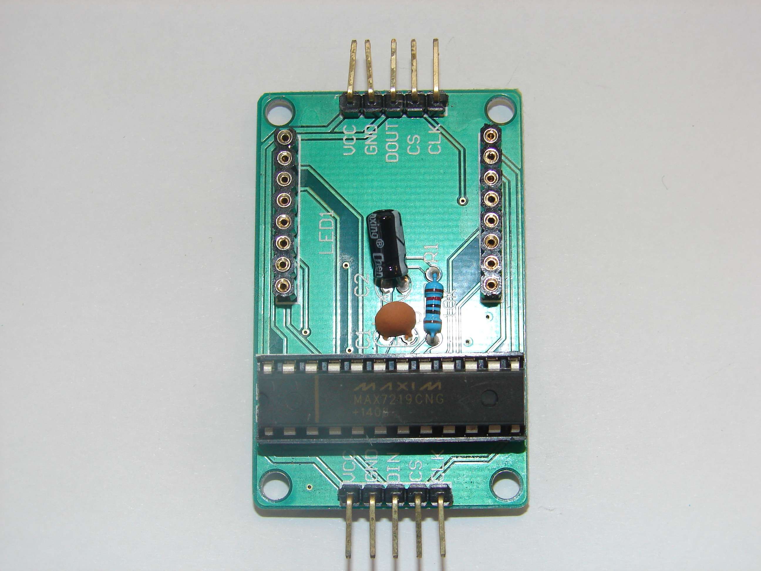
1 is a block left input port, an output port on the right .
2 When control of a single module , simply input port receiving CPU
When cascading multiple modules 3 , output and input termination CPU, the input output termination module of the first two modules of the first one , the first two modules of terminating the input of the first three modules , and so on . ..
To 51 single example:
VCC → 5V
GND → GND
DIN → P22
CS → P21
CLK → P20
Shipping list :
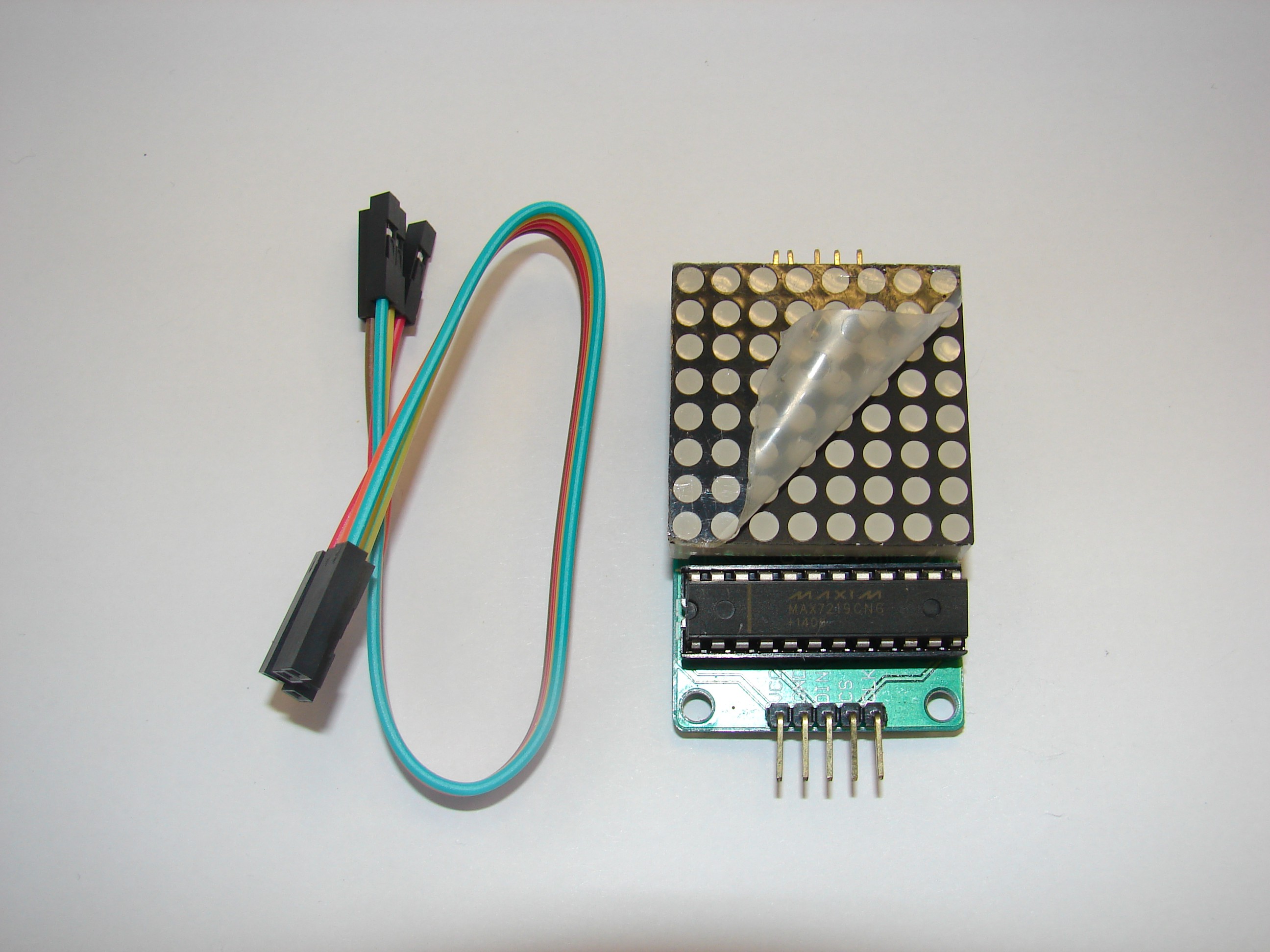
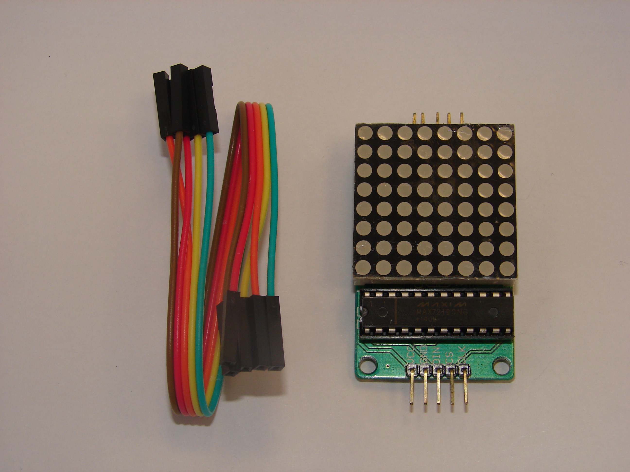
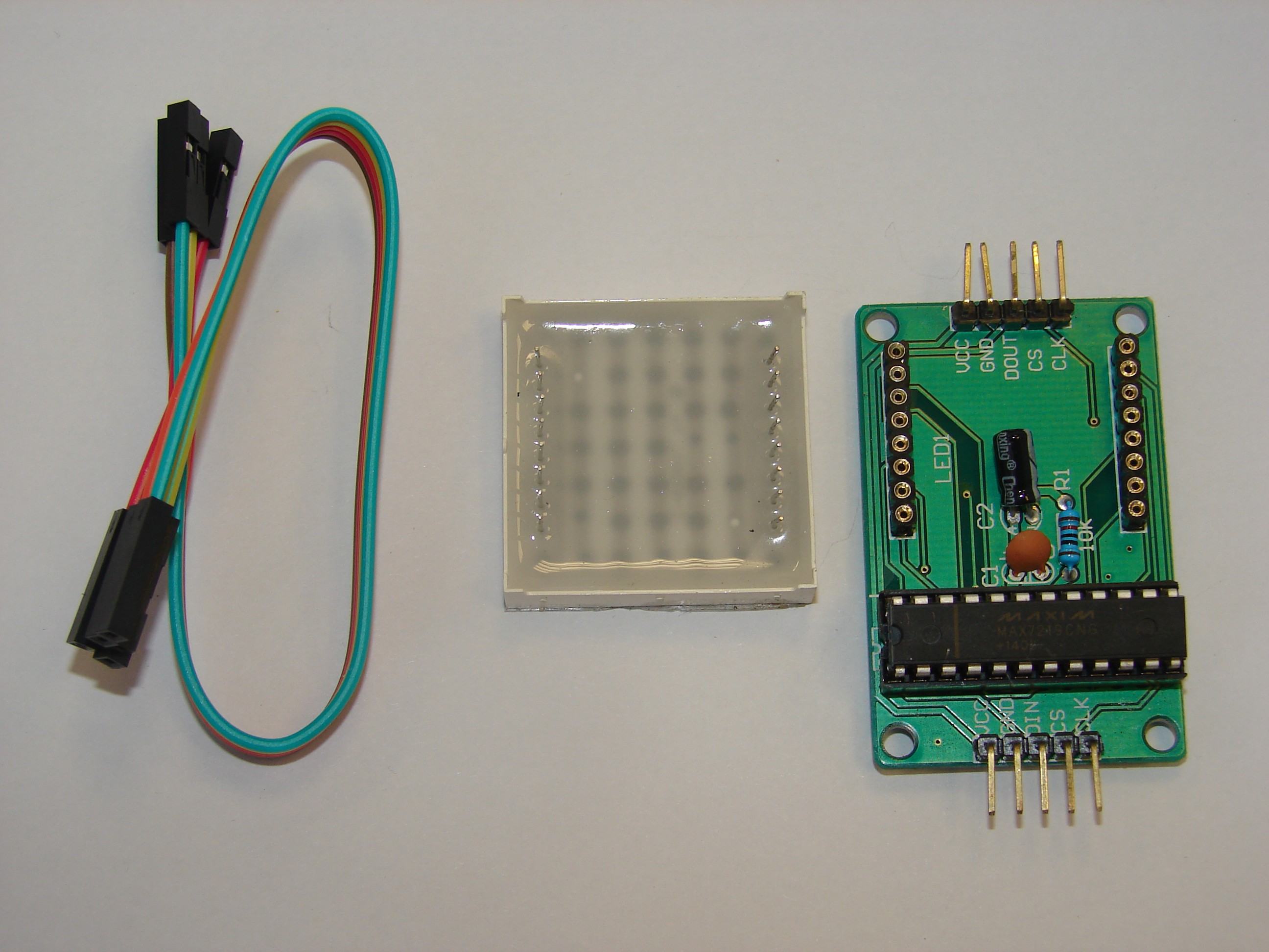
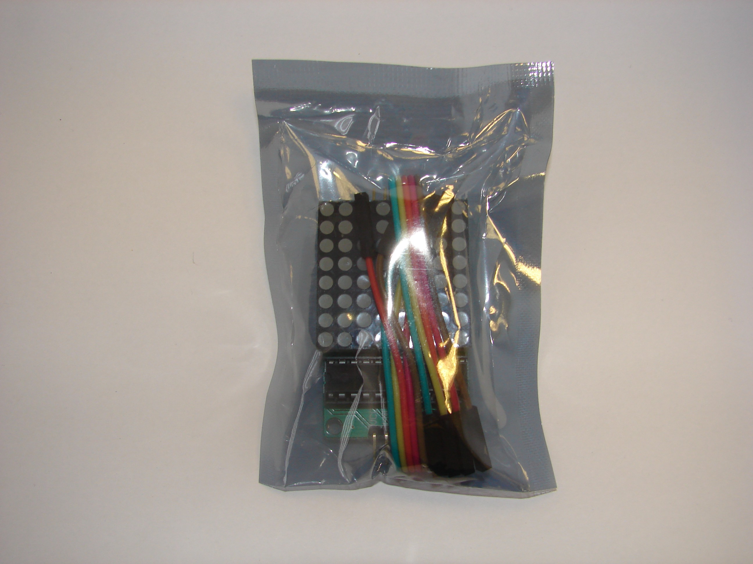
1 x MAX7219 dot matrix module 10 ( finished with lattice , has tested well )
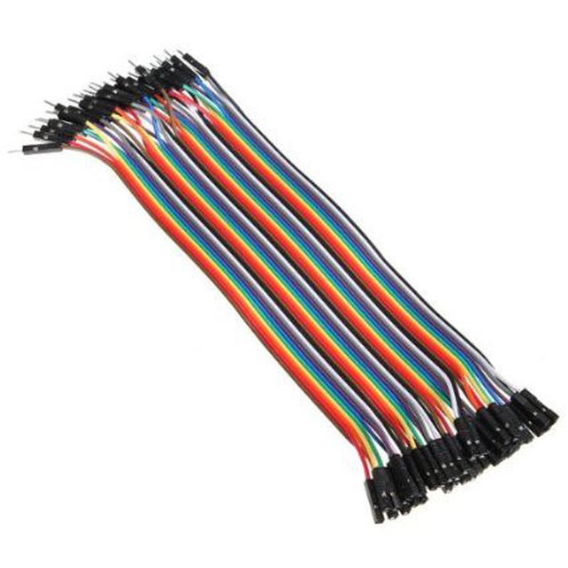
1 x DuPont line 50

